Cisco ACI overview and considerations when deploying single, multi-site or multi-pod designs
Designing and deploying Cisco ACI can be done in a lot of different ways. There is really no right and wrong here when it comes to the deployment model. There is just a list of requirement that best fits the chosen model.
As Cisco ACI has been around for several years now, it got more mature and is been seen more and more in the enterprise market.
I’ll try to help you decide on how to deploy Cisco ACI in a way that matches your requirements.
The Cisco ACI solution is trying to help you solve certain obstacles while still meeting your requirements to align with your “Business model”.
The trouble with your requirements and “Business model” is that the existing network is not always ready to support the use case that your new business critical applications require and the last thing you can do is delay the deployment of an application that is going to make the business money. That’s when we deploy solutions that start to push the boundaries of the original design with configurations that sometimes give operational teams sleepless nights fixing.
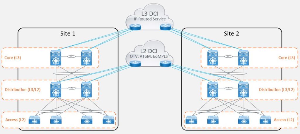
The most common ‘workaround’ being the stretching of layer 2 boundaries between datacenters to provide an active/active state for workloads, compute and storage where devices need to share the same IP subnet in order to operate. Now there were many different ways of achieving this when the requirement first hit the scene. It was often a ‘VPLS’ or ‘AToM’ (Any Transport over MPLS) circuit which doesn’t isolate the spanning-tree topology. Then there was ‘Overlay Transport Virtualization’ (OTV) and ‘FabricPath’. The list goes on but ultimately what all of these options provided was a level of complexity when it came to supportability.
Cisco ACI was designed to address some of these issues by abstracting much of the complex configuration and hiding it under the hood. This is done by provisioning data center connectivity using a software defined network approach (using vxlan). This allows you to programmatically configure your network in a uniform manner.
When Cisco ACI first hit the market, the number of deployment models available were limited. To achieve an active/active data center with workload mobility, the only option available was referred to as ‘Stretched Fabric’. This model took a single fabric with a single APIC cluster and stretched it across multiple datacenter locations. The fabric connectivity consists of a partial mesh of leaf and spine switches whereby not every leaf is connected to every spine as per the traditional Clos topology.
Clos topology
In this Clos topology, every lower-tier switch is connected to each of the top-tier switches in a full-mesh topology. If there isn’t any oversubscription taking place between the lower-tier switches and their uplinks, then a non-blocking architecture can be achieved. The advantage of the Clos network is you can use a set of identical and inexpensive devices to create the tree and gain high performance and resilience that would otherwise cost must more to construct. To prevent any one uplink path from being chosen, the path is randomly chosen so that the traffic load is evenly distributed between the top-tier switches. If one of the top tier switches were to fail, it only slightly degrades performance through the data center.
The main advantages of this deployment approach were that businesses could maintain end-to-end consistent policy. Whilst there were a number of disadvantages, some of the main considerations were around the scalability of the fabric and this approach meant that fault domains were extended between locations. It also meant that some leaf switches had to be dedicated to the transit function (to interconnect leaf and spine switches), and therefore could not be used to host compute functions.
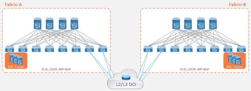
The other option was to deploy two separate fabrics, known as a ‘dual fabric’ topology. This model hosts independent APIC clusters within each datacenter to provide fault domain isolation from the network stack but with the emphasis on achieving active/active or active/standby applications through the capabilities of complimentary technologies within the network such as DNS load balancing. Workload mobility between data centers isn’t a function that this topology supports out of the box without extending the layer 2 constructs across the DCI as per legacy models which many people will want to avoid.
The main advantage of this deployment approach were that businesses could achieve scalability whilst providing a level of fault domain isolation. The main disadvantage of this approach is that end-to-end policy is difficult to achieve with the administrative overhead of having to configure each fabric independently. Admittedly, the administrative burden of replicating policy can be overcome through automation and orchestration, but many businesses do not have this functionality in place within the network space prior to adopting Cisco’s ACI solution.
With these deployment models available, network architects and engineers had to take all of the following considerations into account before deciding which deployment model is suitable:
- Dedicated fabric hardware
- Fault domain isolation
- Latency
- Scalability
- Consistent End-to-End Policy
- Existing Datacenter cabling topologies
Cisco listened to the considerations of its customers and produced the first major enhancement to the ACI stretched fabric deployment option within the datacenter.
Cisco’s solution : Cisco ACI Multi-Pod
This option gave its customers the ability to address some of the inefficiencies of the original stretched fabric design and to make use of those spare ports in their spine switches for connectivity to a common ‘IP network’ (also known as an IPN). The IPN is an L3 routed multicast interconnect between pods allowing you to achieve an active/active datacenter topology (for those stretched subnets) without the requirement for the dedicated leaf roles and addressing scalability considerations, for example, the number of supported leaf nodes.
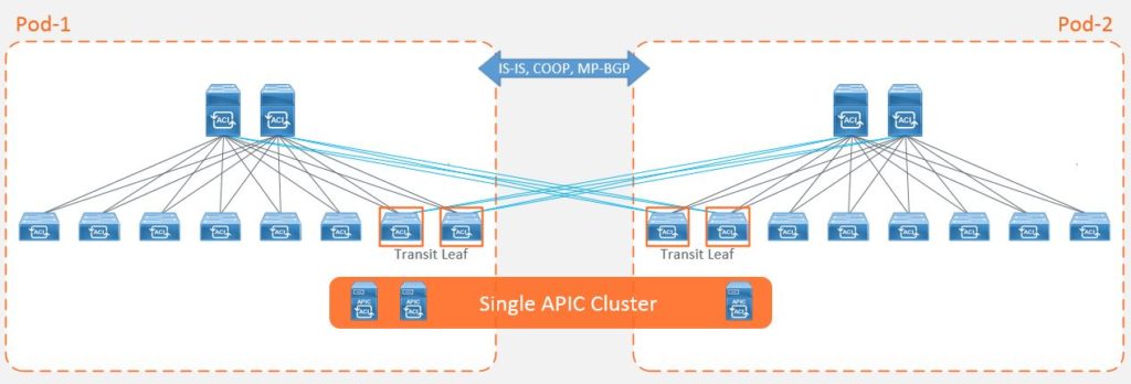
The Cisco ACI Multi-Pod enhancement is the natural evolution of the stretched fabric design that operates by breaking your fabric into ‘Pods’ whilst still using a single APIC cluster. These ‘Pods’ are then interconnected by the routed IPN.
Each pod consists of its own leaf and spine switches, excluding the controllers and operates its own control-plane (ISIS instance and COOP database) providing a level of fault domain isolation, whilst providing consistent end-to-end data-plane policy for traffic forwarding.
A popular deployment consideration that drives this choice of deployment might be physical cabling constraints between data halls within the same datacenter, or a large number of top of rack switches that exceed the leaf scalability limits for a single pod.
One of the main advantages of the Multi-Pod design is the deployment of policy from one APIC cluster to one or more pods. However, this feature may also encourage engineers to consider alternative designs as the pods are treated as a single ‘change domain’ which is comparable to a public cloud availability zone. This means that a configuration error, for example deleting a tenant, would be pushed to all pods, so speed and flexibility of policy deployment comes at a cost. This consideration has driven some customers to deploy multiple Multi-Pod fabrics across the same datacenter locations.
More recently (early 2019), Cisco released the next evolution on the ACI roadmap to address the concerns of interconnecting dual fabrics and providing you with the ability to provision common policy across the separate previously independent fabrics.
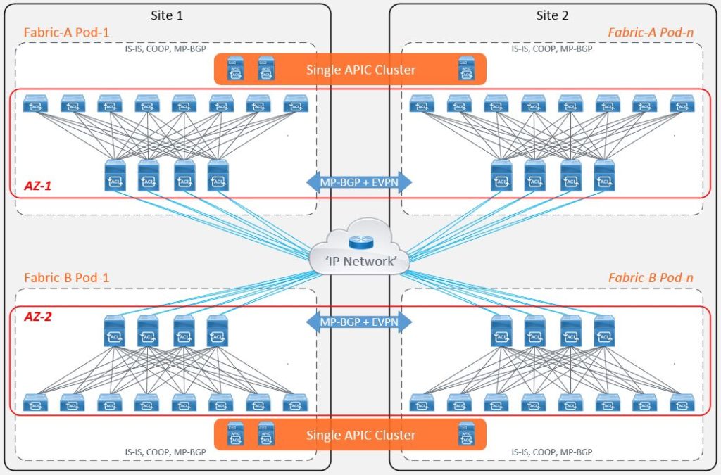
Cisco’s solution : Cisco ACI Multi-Site
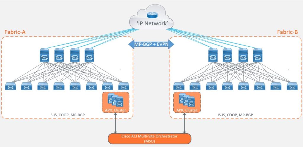
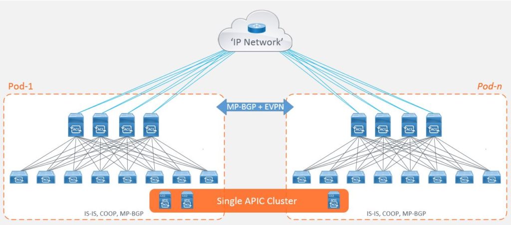
Cisco Multi-Site is the natural evolution of the ‘Dual Fabric’ design that takes on some of the characteristics of a Multi-Pod architecture. This includes active/active stretched bridge domains but with a number of fault domain, change domain and scalability enhancements with the ability to push policy from a single point. Again, taking on board the concept of ‘regions’ from the public cloud providers, Multi-Site works by treating each fabric as a site. Each site is managed by its own local APIC cluster with its own control, management and data-plane logic. It still has the requirement to connect to the IPN, although this time it only requires a unicast topology to interconnect the different sites with each other.
Now that each site is controlled by its own local APIC cluster, this allows the site to maintain its own autonomy from a policy administration perspective, but this doesn’t solve the problem of having to configure each controller cluster separately as is the case with the dual fabric design.
To address this, Cisco introduced the ‘Multi-Site Orchestrator’ (MSO) which is used to program policy and forwarding logic into the APICs and spine switches at each site and provide reachability and consistent end-to-end policy through the use of different External Tunnel Endpoint (ETEP) addresses for each site within the IPN.
The MSO allows policy to be configured once and deployed to different sites at different times. This solution offers change domain isolation but with central policy management.
The most common deployment considerations that drives this choice of deployment might be the ability to deploy the same application across your datacenters that are geographically separated, such as US, EMEA and APAC. Alternatively, you may have 3 datacenters, two active and one ‘Disaster Recovery’ (DR) site, and you want to ensure that policies applied to the 2 active DCs are the same as those deployed within the DR site where you want to ensure that business continuity applications are readily available.
More Cisco ACI considerations
Layer 3 connectivity to the outside can be implemented in one of two ways: by attaching routers to leaf nodes (normally designated as border leaf nodes) or directly to spine switches:
● Connectivity through border leaf nodes using VRF-lite: This connectivity can be achieved with any routing-capable device that supports static routing, OSPF, Enhanced Interior Gateway Routing Protocol (EIGRP), or Border Gateway Protocol (BGP), as shown in Figure 2. Leaf-node interfaces connecting to the external router are configured as Layer 3 routed interfaces, subinterfaces, or SVIs.
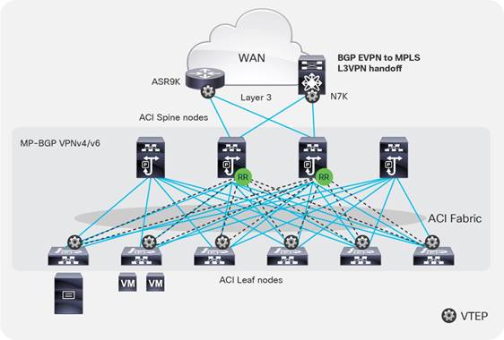
● Connectivity through spine ports with multiprotocol BGP (MP-BGP) EVPN and VXLAN (also known as GOLF): This connectivity option requires that the WAN device that communicates with the spines is MP-BGP EVPN capable. This feature uses VXLAN to send traffic to the spine ports as illustrated in Figure 3. Optionally, it supports OpFlex protocol. At the time of this writing, this topology is possible only with Cisco Nexus 7000 Series and 7700 platform (F3) switches, Cisco® ASR 9000 Series Aggregation Services Routers, or Cisco ASR 1000 Series Aggregation Services Routers. In this topology, there is no need for direct connectivity between the WAN router and the spine. For example, there could be an OSPF-based network in between.
Figure 2. Connectivity to the outside with VRF-lite (standard L3Out in Cisco ACI)
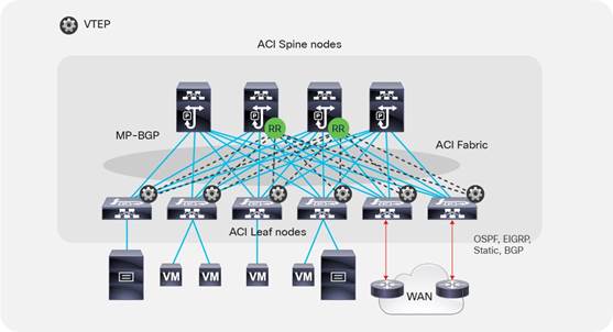
Figure 3. Connectivity to the outside with Layer 3 EVPN services
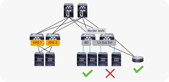
Do not use the L3Out to connect servers
Border leaf switches can be configured with three types of interfaces to connect to an external router:
● Layer 3 (routed) interface
● Subinterface with IEEE 802.1Q tagging
● Switch Virtual Interface (SVI)
When configuring an SVI on an interface of a L3Out, you specify a VLAN encapsulation. Specifying the same VLAN encapsulation on multiple border leaf nodes on the same L3Out results in the configuration of an external bridge domain.
The L3out is meant to attach routing devices. It is not meant to attach servers directly on the SVI of an L3Out. Servers should be attached to EPGs and Bridge Domains (BDs).
There are multiple reasons for this:
● The L2 domain created by an L3Out with SVIs is not equivalent to a regular bridge domain.
● The L3ext classification is designed for hosts multiple hops away.
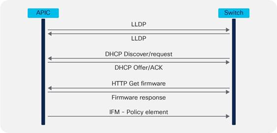
Leaf or spine bootup sequence
APIC clustering
APICs discover the IP addresses of other APICs in the cluster using an LLDP-based discovery process. This process maintains an appliance vector, which provides mapping from an APIC ID to an APIC IP address and a universally unique identifier (UUID) for the APIC. Initially, each APIC has an appliance vector filled with its local IP address, and all other APIC slots are marked as unknown.
Upon switch reboot, the policy element on the leaf switch gets its appliance vector from the APIC. The switch then advertises this appliance vector to all its neighbors and reports any discrepancies between its local appliance vector and the neighbors’ appliance vectors to all the APICs in the local appliance vector.
Using this process, APICs learn about the other APICs connected to the Cisco ACI fabric through leaf switches. After the APIC validates these newly discovered APICs in the cluster, the APICs update their local appliance vector and program the switches with the new appliance vector. Switches then start advertising this new appliance vector. This process continues until all the switches have the identical appliance vector, and all of the APICs know the IP addresses of all the other APICs.
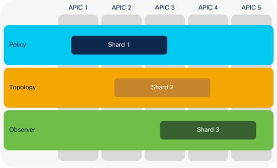
Cluster sizing and redundancy
To support greater scale and resilience, Cisco ACI uses a concept known as data sharding for data stored in the APIC. The basic theory behind sharding is that the data repository is split into several database units, known as shards. Data is placed in a shard, and that shard is then replicated three times, with each replica assigned to an APIC appliance, as shown in this Figure.
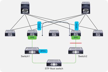
Spanning Tree Protocol considerations
The Cisco ACI fabric does not run Spanning Tree Protocol natively, but it can forward BPDUs within the EPGs.
The flooding scope for BPDUs is different from the flooding scope for data traffic. The unknown unicast traffic and broadcast traffic are flooded within the bridge domain; Spanning-Tree-Protocol BPDUs are flooded within a specific VLAN encapsulation (also known as FD_VLAN), and in many cases, though not necessarily, an EPG corresponds to a VLAN.
This figure shows an example in which external switches connect to the fabric.
Fabric BPDU flooding behavior
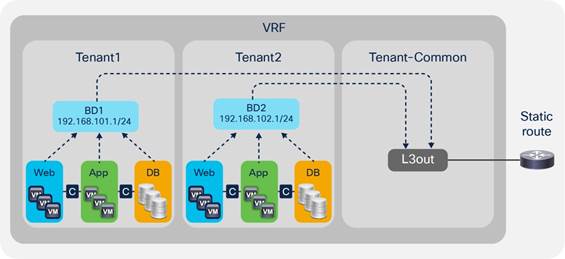
VRFs and bridge domains in the common tenant
In this scenario, you create the VRF instance and bridge domains in the common tenant and create EPGs in the individual user tenants. You then associate the EPGs with the bridge domains of the common tenant. This configuration can use static or dynamic routing.
The configuration in the common tenant is as follows:
- Configure a VRF under the common tenant.
- Configure an L3Out connection under the common tenant and associate it with the VRF.
- Configure the bridge domains and subnets under the common tenant.
- Associate the bridge domains with the VRF instance and L3Out connection.
The configuration in each tenant is as follows:
- Under each tenant, configure EPGs and associate the EPGs with the bridge domain in the common tenant.
- Configure a contract and application profile under each tenant.
Shared L3Out connection through the common tenant with a VRF instance and bridge domains in the common tenant.
This approach has the following advantages:
● The L3Out connection can be configured as dynamic or static.
● Each tenant has its own EPGs and contracts.
This approach has the following disadvantages:
● Each bridge domain and subnet is visible to all tenants.
● All tenants use the same VRF instance. Hence, they cannot use overlapping IP addresses.
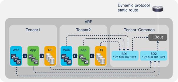
VRFs in the common tenant and bridge domains in user tenants
In this configuration, you create a VRF in the common tenant and create bridge domains and EPGs in the individual user tenants. Then you associate the bridge domain of each tenant with the VRF instance in the common tenant. This configuration can use static or dynamic routing.
Configure the common tenant as follows:
- Configure a VRF instance under the common tenant.
- Configure an L3Out connection under the common tenant and associate it with the VRF instance.
Configure the individual tenants as follows:
- Configure a bridge domain and subnet under each customer tenant.
- Associate the bridge domain with the VRF in the common tenant and the L3Out connection.
- Under each tenant, configure EPGs and associate the EPGs with the bridge domain in the tenant itself.
- Configure contracts and application profiles under each tenant.
Shared L3Out connection with the VRF instance in the common tenant
The advantage of this approach is that each tenant can see only its own bridge domain and subnet. However, there is still no support for overlapping IP addresses.
Best practices summary from the Cisco Website :
This section summarizes some of the best practices presented in this document and provides a checklist you can use to verify configuration settings before deploying a Cisco ACI fabric:
● Physical design of the fabric: Consider from the beginning how you want to organize leaf nodes in vPC peers, and how you want to provide routed connectivity to the outside: with MP-BGP EVPN (GOLF) or VRF-lite.
● Physical design of the fabric: Consider whether you need to use a dedicated border leaf node or the border leaf should also be a computing leaf node.
● Controller design: Consider how many controllers you need based on scalability and high availability and be aware of how configuration and run-time data are saved and can be recovered.
● Fabric access design: Consider the choice of the infrastructure VLAN and of the TEP pool. Consider the use of per-VLAN MCP to eliminate loops and be sure that you understand how Spanning Tree Protocol interacts with the Cisco ACI fabric.
● Object configuration for multiple tenants: If you need to configure objects to be used by multiple tenants, you should configure them in the common tenant, but make sure you understand how object names are resolved and the use of contracts with global scope.
● Tenant design: If you migrate an existing network to Cisco ACI, you can configure tenants with a network-centric approach, which makes migration easier. If you plan to migrate later with more segmentation, you should consider instead reducing the number of bridge domains by merging more subnets into the same bridge domain. When merging bridge domains, you should consider Flood in Encapsulation to limit the scope of flooding.
● Tenant design with VRF: Consider whether you want to use VRF in the common tenant, or whether you want a VRF per tenant. Make sure that you know how to choose between ingress and egress filtering on the VRF. At the time of this writing, most features are designed to work with VRF configured for ingress filtering.
● Tenant design with bridge domain: When creating a bridge domain, be sure to associate the bridge domain with a VRF instance even if you intend to use the bridge domain only for Layer 2 switching. Make sure you understand how Cisco ACI dataplane learning works with or without IP routing and how ARP optimizations work. Then tune the bridge domain accordingly. In most cases, you can optimize flooding by using hardware-proxy, by keeping IP routing enabled, and a subnet configured in the bridge domain.
● Bridge domain subnet: Define one subnet as primary. Do not configure more than one MAC address unless you need to do so for Layer 2 extension. The subnet used as the default gateway should always be configured under the bridge domain.
● Tuning bridge domains: Be careful when changing bridge domain settings because several optimization options can be disruptive. At the time of this writing, changing the bridge domain configuration from hardware-proxy to unknown unicast flooding and vice-versa is disruptive.
● Dataplane learning: In the presence of active/active NIC teaming (other than vPC) and in the presence of floating IP addresses, you may need to tune the VRF or the bridge domain for dataplane learning.
● EPGs and access ports: When associating EPGs with bare-metal servers, use Access (untagged) as the access-port option with Cisco Nexus 9300-EX and Cisco Nexus 9300-FX (or newer) platform switches. With first-generation leafs, you should use 802.1p for access ports.
● EPG and contracts: For migration purposes, make sure you understand the options of VRF unenforced, Preferred Groups, and vzAny.
● Contracts: Make sure you understand the relative priorities of contracts between EPGs, or between vzAny and the rule priority of permit, deny, and redirect.
● Deployment and Resolution Immediacy: Consider the Resolution and Deployment Immediacy On-Demand option for most workloads to limit the consumption of hardware resources. Consider the Resolution Immediacy Pre-Provision option for management connectivity. Configure different vDSs for management connectivity and for virtual workload connectivity.
● VRF sharing: If you plan to configure shared services using route leaking between tenants and VRF instances, you also need to enter subnets or /32 under the EPG that is the shared services provider, but be sure that each EPG subnet is not overlapping with the other EPGs.
● L3Out design: Make sure you understand the interactions between L3Our, vPC, SVI encapsulation, and routing in order to define correctly the L3Out configuration.
● Multiple L3Outs and L3External: Make sure you understand how the L3external works with multiple L3Outs.
For more information, please refer to https://www.cisco.com/go/aci.
